200 MHz
PCBITE-6019
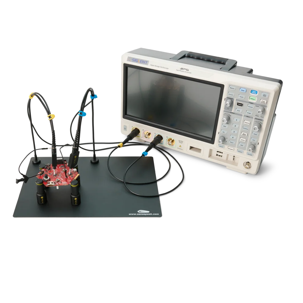
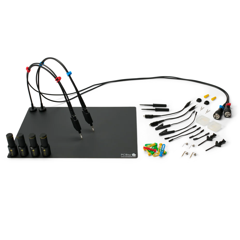
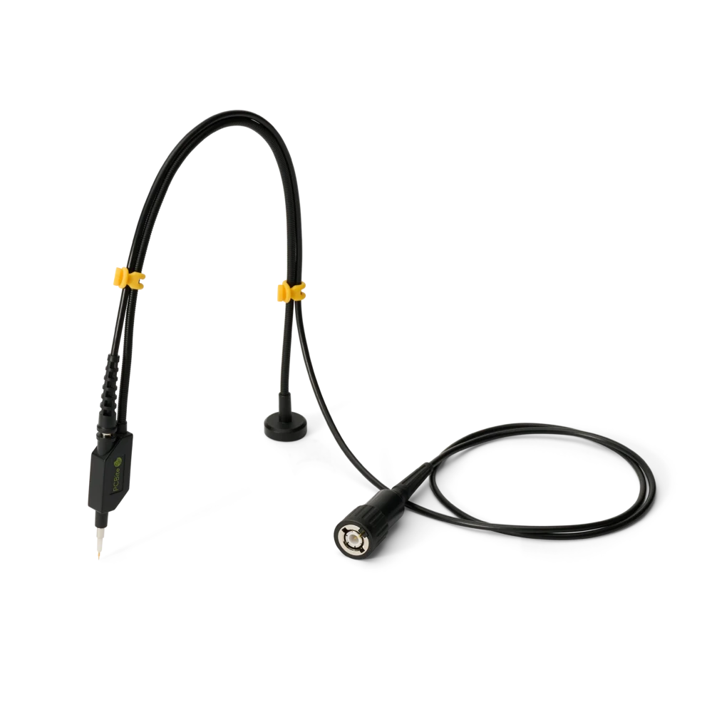
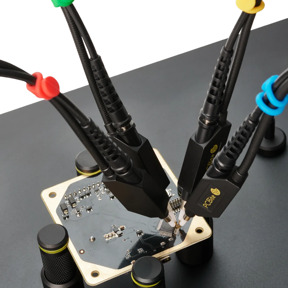
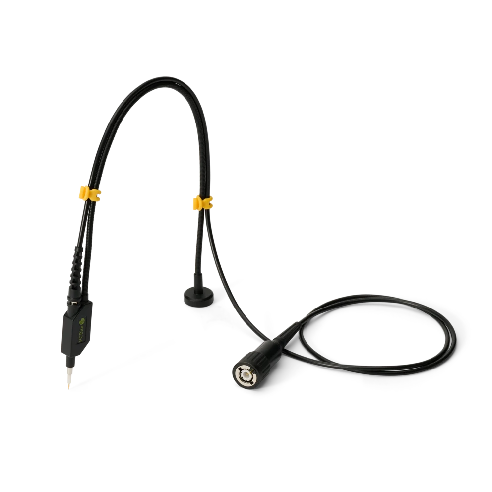
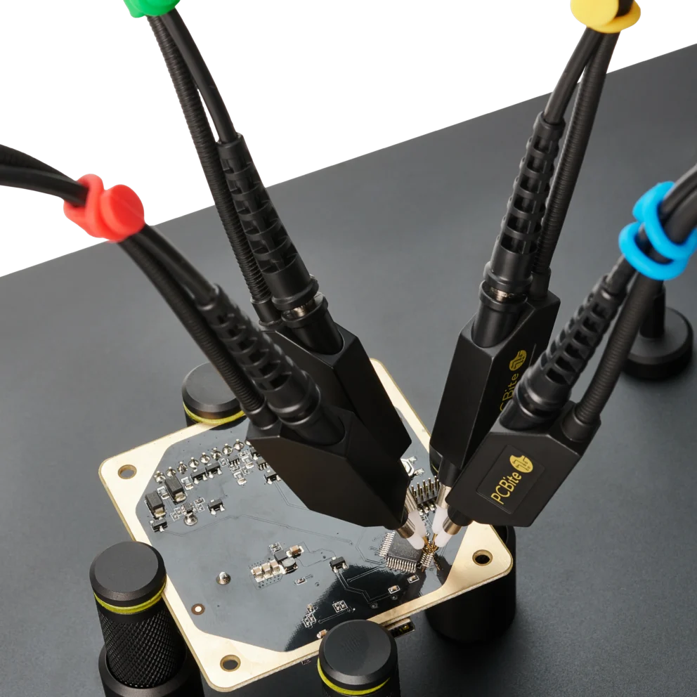
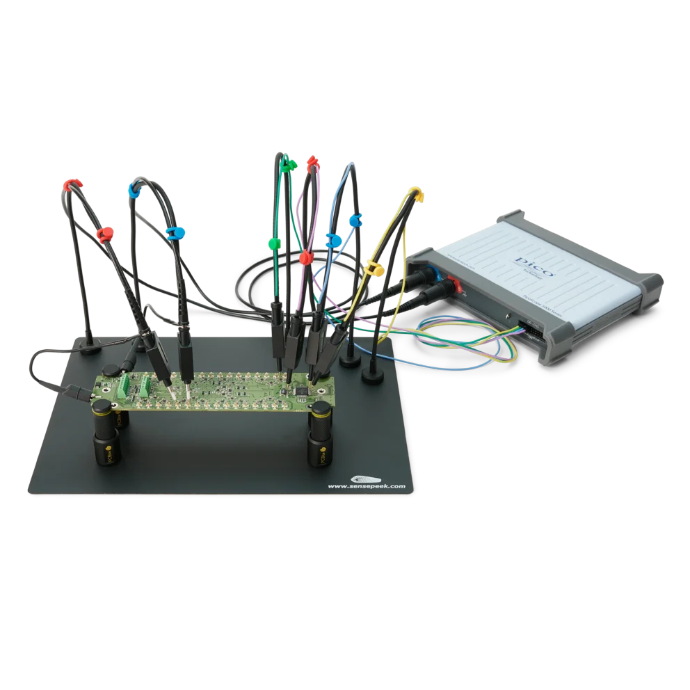
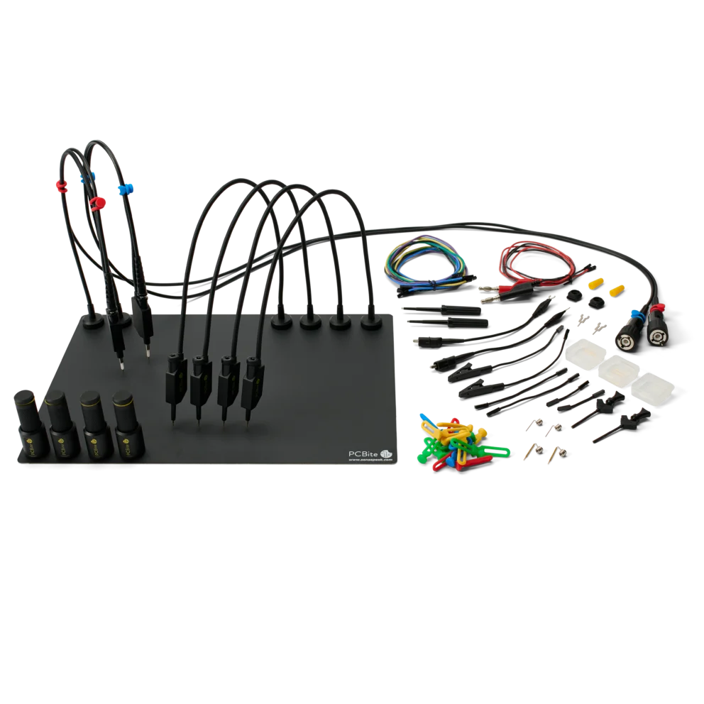
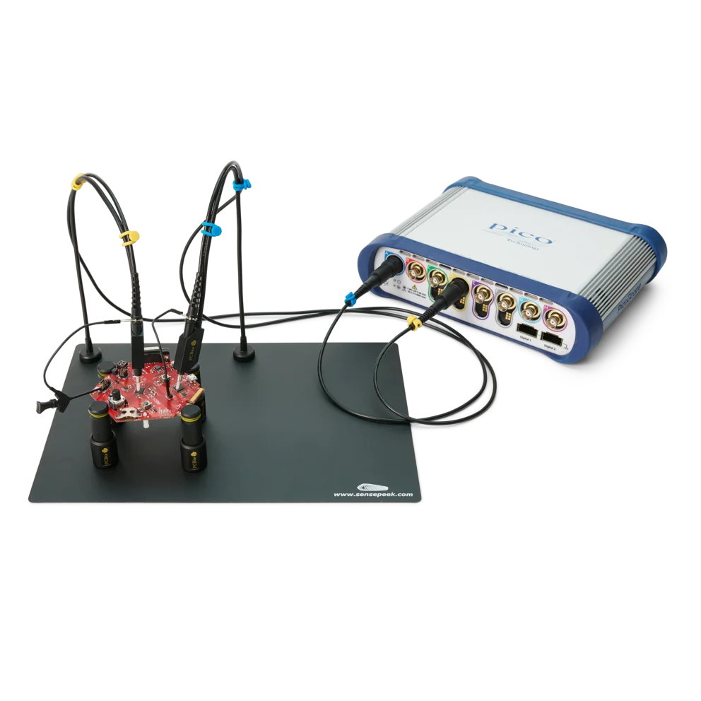
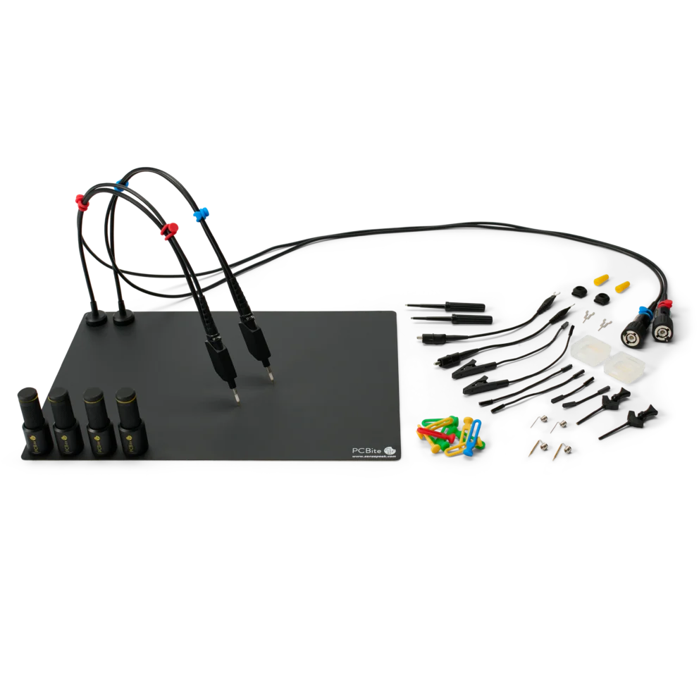
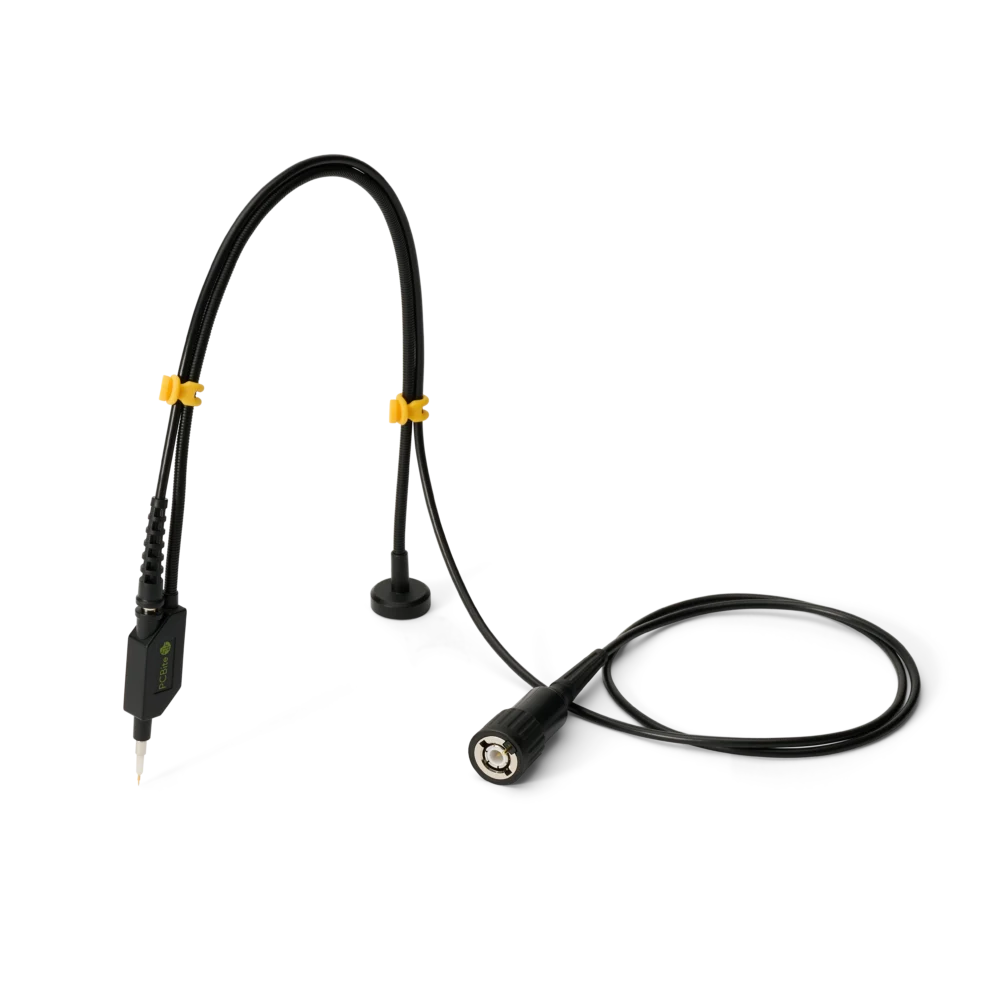
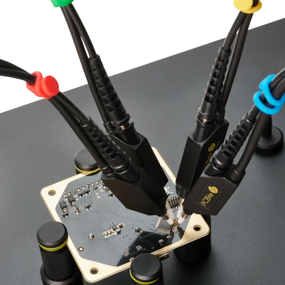
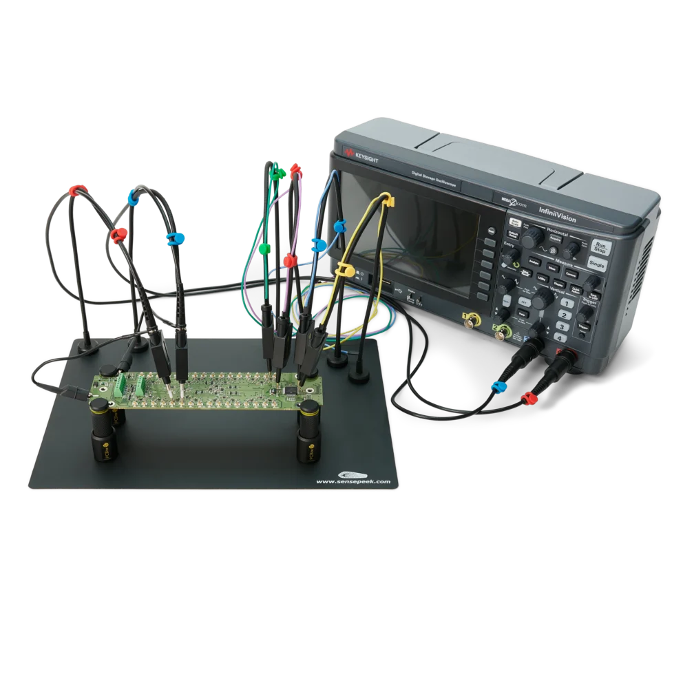
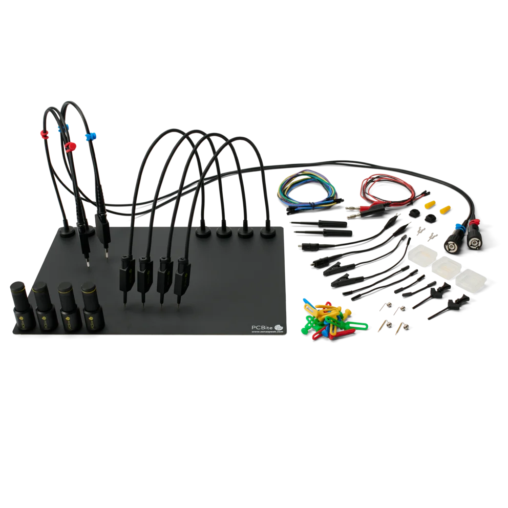
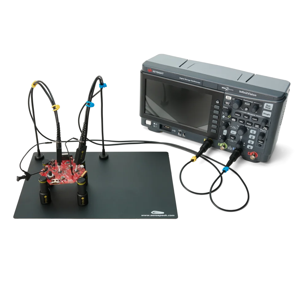
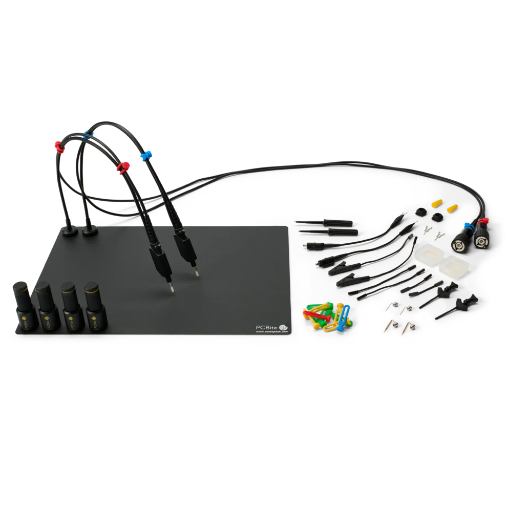
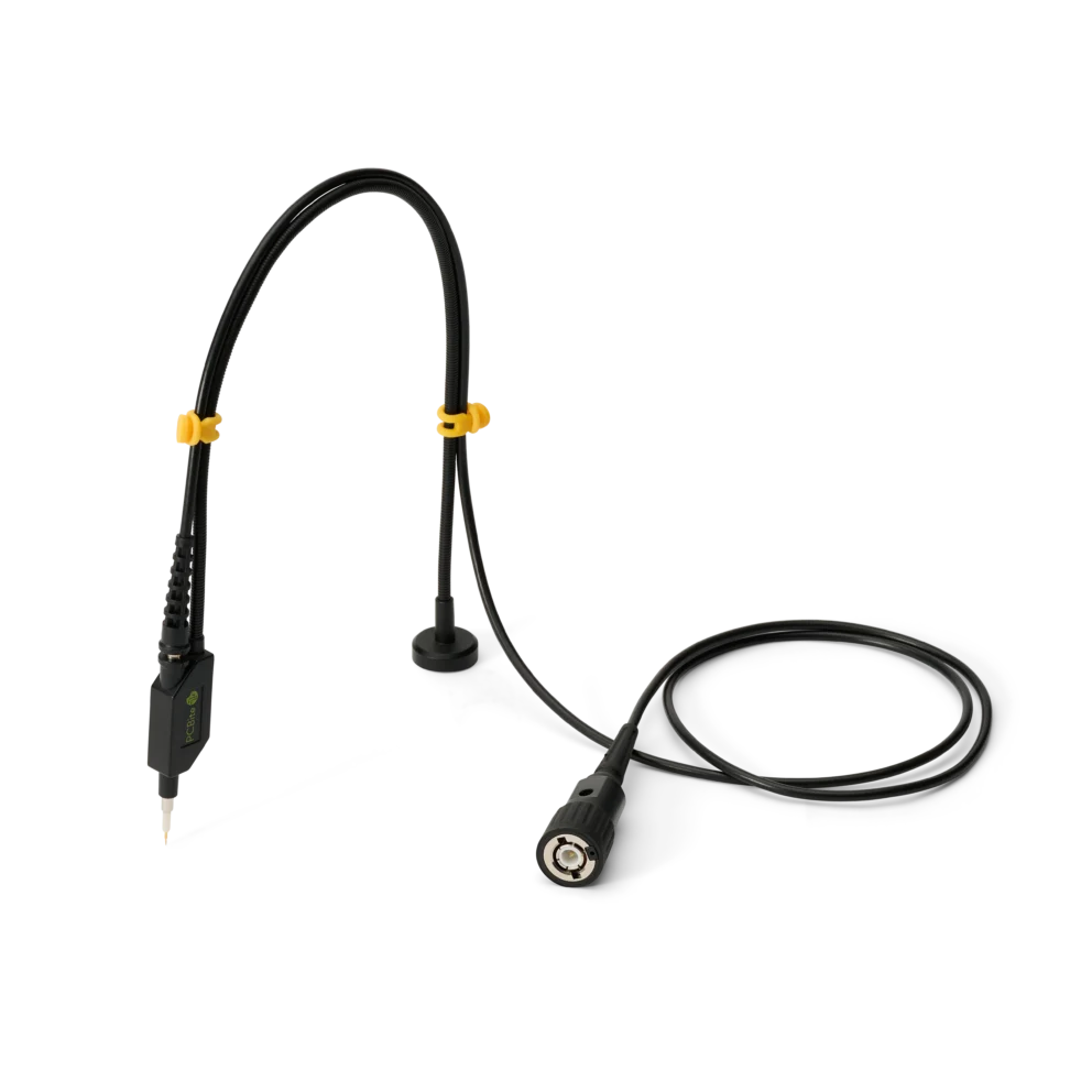
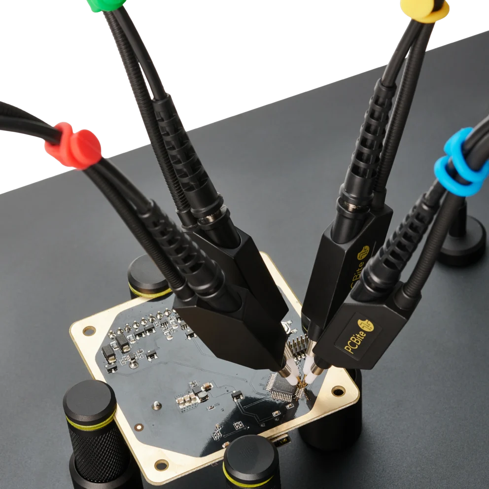
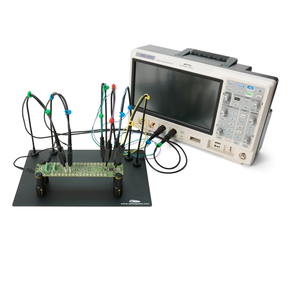
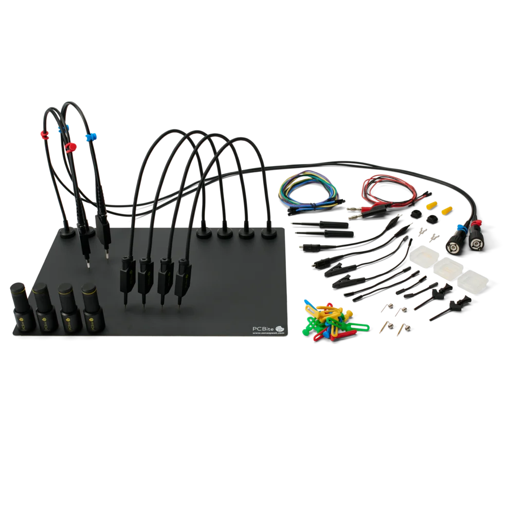
PCBite kit with 2x SQ200 200 MHz and 4x SQ10 handsfree probes
279 €
In stock
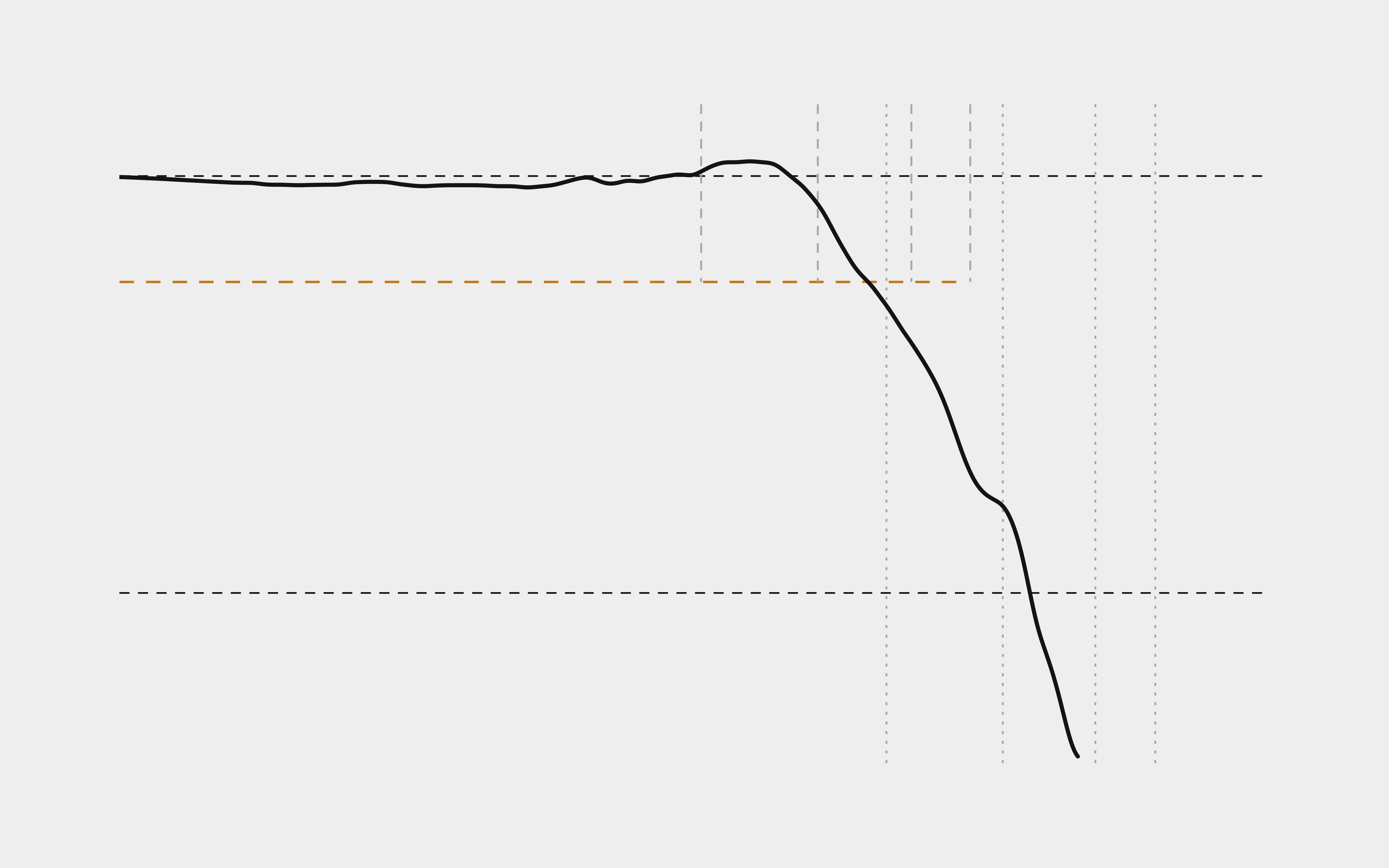
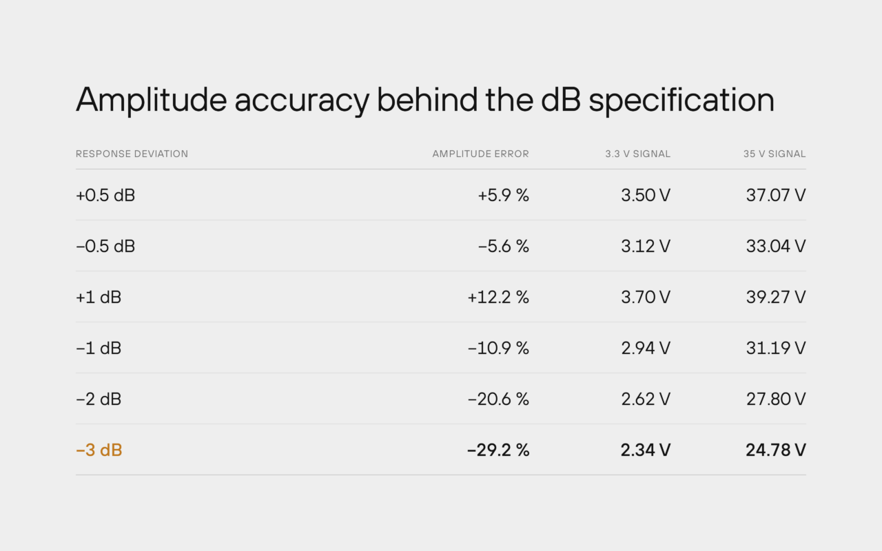
Bandwidth and flatness describe different parts of probe performance. Bandwidth defines the -3 dB point. Oscilloscope probe bandwidth is normally specified at the frequency where sine-wave amplitude has fallen by 3 dB. At that point the displayed amplitude is about 70.7 % of the low-frequency value.
Flatness defines the permitted amplitude deviation over a specified frequency range and therefore describes amplitude accuracy across the usable range before the bandwidth limit.
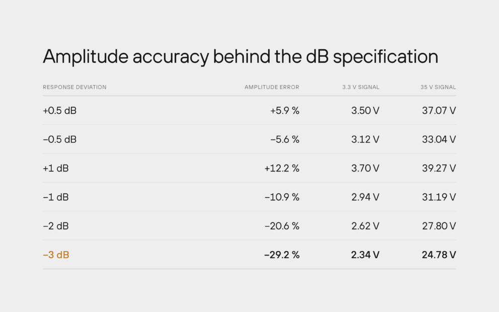
A 0.5 dB response deviation corresponds to approximately +5.9 % or -5.6 % in measured amplitude.
Sensepeek oscilloscope probe specifications include flatness data over defined frequency ranges in addition to nominal bandwidth, showing amplitude performance across the usable range before the -3 dB point.
A passive 10:1 probe uses a resistive divider together with the oscilloscope input. The capacitive divider must match the same ratio for a flat frequency response.
Oscilloscope input capacitance and probe cable capacitance are part of the compensation. Because input capacitance varies between oscilloscopes, a trim capacitor matches the probe to the connected instrument.
If the resistive and capacitive dividers are not aligned, the response becomes uneven and the measured waveform no longer represents the input correctly.
The probe should be compensated before first use and before important measurements. Moving it to a different oscilloscope requires compensation again.
Most oscilloscopes provide a probe-compensation square-wave output, typically around 1 kHz. Connect tip and ground, then adjust the compensation capacitor with a non-conductive tool while observing the waveform.
Correct compensation produces horizontal tops and clean edges. Overcompensation shows overshoot; undercompensation shows undershoot or a sagging edge. Adjustment may require only a small fraction of a turn.
The square wave contains low- and high-frequency components, making compensation errors visible directly in the waveform.
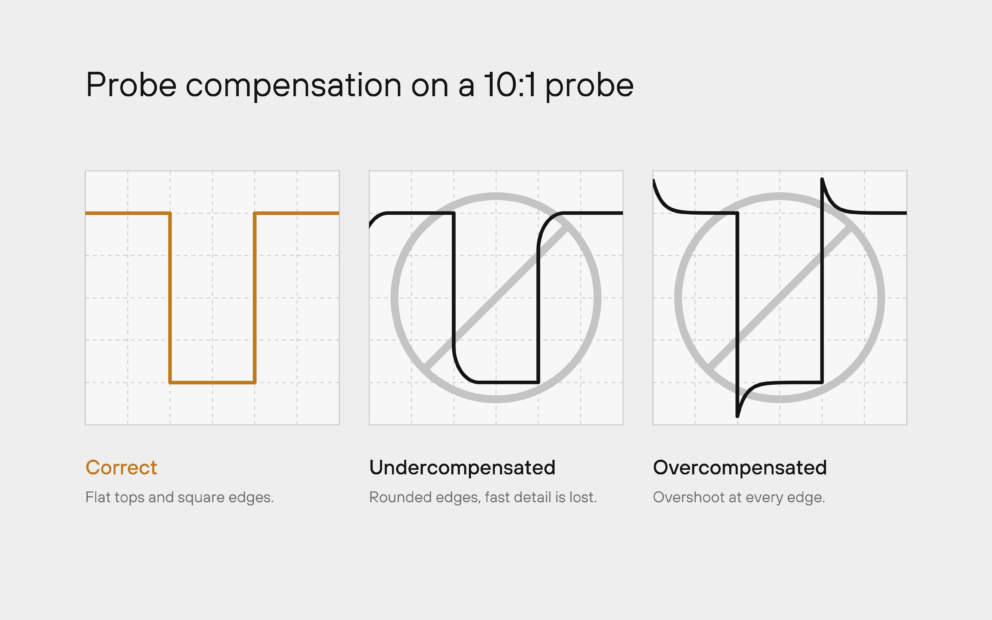
Fig. 2. Proper, under- and overcompensation of a 10:1 probe.
Compensation error and flatness
Incorrect compensation changes the frequency response. Overcompensation can introduce gain, while undercompensation can attenuate parts of the response before amplification appears at higher frequencies.
Flat response is a property of the complete probe and oscilloscope input network. Compensation should therefore be performed on the oscilloscope used for the measurement.
Du använder en föråldrad webbläsare. Alla funktioner fungerar inte i din webbläsare. Var vänlig uppgradera din webbläsare för att förbättra din upplevelse och öka din säkerhet.